By Richard Huss
In May’s model of the month Richard Huss takes us through an ingenious representation of the Vale of Rheidol trestle bridge that could be implemented in many garden railway settings.

Wrightscale Wren and tippers at Pont Siriol, on the Elmdon Heath Light Railway
During my student days in Aberystwyth, a favourite Sunday afternoon stroll was down to the Afon Rheidol near Llanbadarn, where the Vale of Rheidol railway crosses the river on a wooden trestle bridge. Nothing as fancy as some of the vast trestles you get on narrow gauge lines in the States – but very pleasant nevertheless. Following the sale of the line by BR in 1989, the bridge was entirely rebuilt in very similar style to the original; more recently, a foot/cycle bridge in a not entirely sympathetic style has been built just downstream.
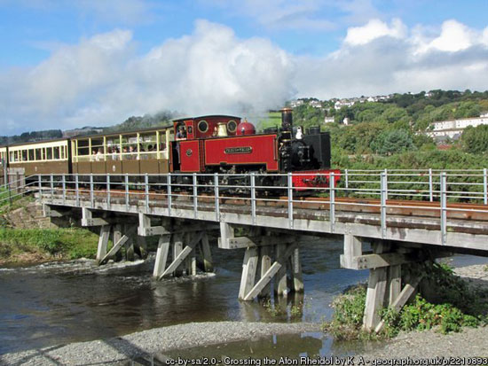
The real-life Rheidol trestle bridge
As construction of the Elmdon Heath Light Railway began in 2011, thoughts turned to a rather awkward corner of the garden and the matter of bridging the garden path. The bridge here would need to be on the skew, with a rather awkward transition to the adjacent section of terra firma which was to be built on a pre-existing railway sleeper supporting a raised bed. It also needed to be removable, to let the wheelie bin, wheelbarrow etc. through.
In fact, this was almost the first part of the line to be built, as I decided I needed to check that this corner could in fact be bridged before building the rest of the line: it would be a terrible shame to get 95% of the way round the garden and discover the last 5% wouldn’t work…
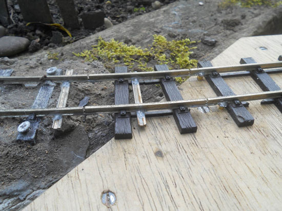
An oddment of wood was tried in place, and some Peco SM32 track tentatively encouraged into place. Measurements were taken. The bridge would need a bit of a curve at one end, and at that end the transition from bridge to solid ground would indeed be potentially awkward, but it might work.
The gap to be bridged – note the nasty angle at which the track has to join the bridge
The bridge needed to be around 5’6” long, but only 8” high. Not entirely unlike… the Rheidol bridge – might that prove a suitable prototype? Time to turn to the internet.
One of the best sources of information turned out to be Geograph – a web site where users can post photos, linking them to a grid reference. Grid reference SN6080 (http://www.geograph.org.uk/gridref/SN6080) turned up loads of photographs of the bridge in question – including some very useful angles showing many of the constructional details.
I also found on my bookshelves an article in Model Railway Journal No. 57 (1992) about the trestle bridges on the Cambrian Railway – not the same as the Rheidol example, but again very useful on typical construction details and timber sizes.
Finally, an article on the US web site “Family Garden Trains” provided a lot of useful information on building US-style trestle bridges: http://familygardentrains.com/primer/bridges/trestle/trestle.htm

Some of the underneath details of the Rheidol bridge
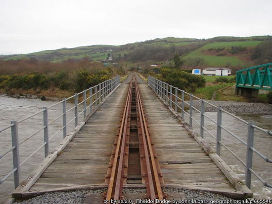
An extremely useful end-on view of the Rheidol bridge, from which the width could be estimated quite accurately since the track gauge is known
From these sources, especially the photographs of the actual bridge in question, I came up with a drawing of a Rheidol-style trestle “bent” that looked about right, and could be built from timber sections readily available at a nearby DIY store. Visually, the idea seemed plausible. But could it be strong enough to withstand both the weight of trains, and regularly being moved? Given the gravel path, which additionally sloped slightly in both directions, I couldn’t rely on the ground for support, which needed to be provided through the abutments.
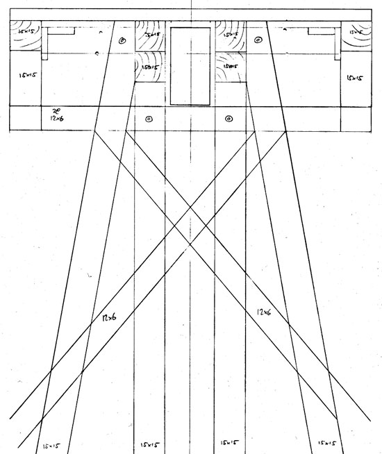
Drawing of intended Rheidol-style trestle bents
The eventual solution was, of course, to cheat. What I’ve built looks like a Rheidol-style trestle bridge. It’s actually a big chunk of 1 ½” x ¾” aluminium box section with a wooden deck on top, and some pretty wooden bits underneath for show. Edwards Metals in Aston (http://www.edwardsmetals.co.uk/) were contacted and an order was placed.
Very careful measurements were taken and plotted of the curve required (actually a series of straight lines between the individual trestle bents), and the position of the reinforcing beam was worked out. Given the curve, the beam is approx. 15mm off-centre at either end, and in the middle a maximum of 15mm off-centre to the other side. The bridge deck could then be made, of 6mm ply with 15x15mm timber reinforcing it underneath.
And then the metalwork started. Behind these timber beams is a framework of 5/8” x 5/8” aluminium angle, cut and bent to follow the curve of the bridge, with cross-members of the same section added adjacent to where the trestle bents would be located.
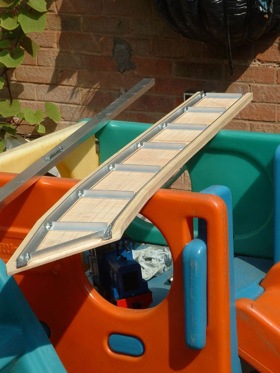
The bridge deck, upside down, before adding the box section reinforcement
The box section could then be clamped in position and its position marked on the cross members. Plenty of M4 countersunk screws hold the whole thing together.
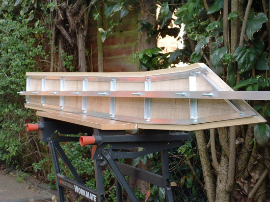
The nearly-finished bridge deck, just waiting for the main beam to be cut to length.
Quite the hardest part of the whole process, by a large margin, was preparing the abutments on which the bridge rests. These are made from offcuts of the same 1½” x ¾” box section, coach bolted to the trackbed. A locating slot cut into the top and front faces, into which the bridge beam fits, locates the bridge accurately, while the side angles under the edges of the deck rest on top of the abutments and provide lateral stability. Lateral stability was particularly important given the angle at which the curved end of the bridge met the abutment. The “straight” one was bad enough, lots and lots of chain drilling and filing – but the angled one was an absolute pig and took ages. But it did, in the end, fit – and accurately.
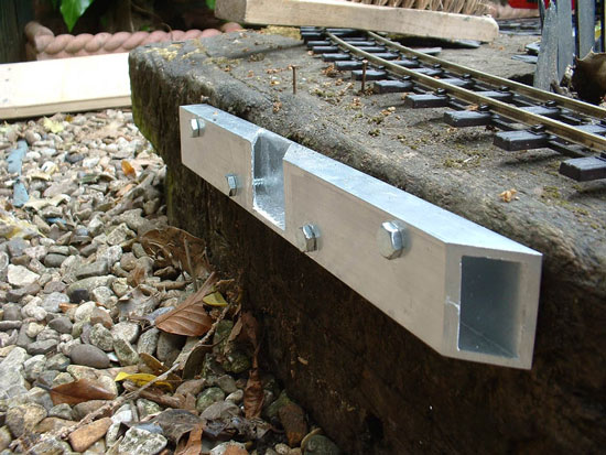
The angled abutment – locating slot fashioned by hand, which was really quite tedious
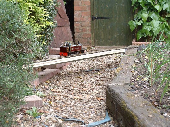
“Wilberforce” (Roundhouse “Millie” class) becomes the first steam loco to run onto the unfinished bridge
From then on it was just a case of adding the decorative bits. My trestle bent drawing was translated into a timber jig on which the bents could be constructed of 15x15mm and 12x6mm timber sections. These were partially built in the jig (the four piles and the cross braces on one side), fixed with waterproof PVA glue, and then removed for addition of the remaining cross braces. Once dry, the joints were pinned as well, and the short uprights that support the outer edges of the bridge deck were added. The bents (and the deck as well) were then liberally treated with Cuprinol Clear.
Trestle bent building jig of 6mm ply and timber offcuts
In fact no two bents are identical, as there are several different lengths to cope with the sloping path, and the top portions of the two central piles needed to be adjusted to make room for the box section beam.
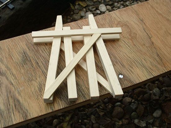
Typical trestle bent glued together, awaiting uprights at the ends, pinning, and wood treatment
The completed trestle bents were then bolted to the bridge structure – yet more tedious cutting and filing of aluminium, this time angle brackets from the remaining portions of the 5/8” x 5/8” angle.
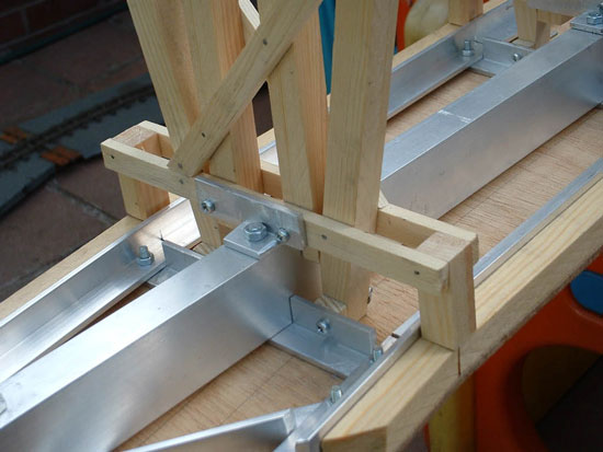
Trestle bent bolted to the upside-down bridge
Tracklaying followed, in Peco SM32. Yes, the Rheidol bridge is laid on longitudinal baulks and is check-railed throughout. One day, perhaps. At the “square” end of the bridge, the rails are soldered to brass screws set into the track deck, and this has provided quite sufficient alignment.
I did try the same at the other end of the bridge, but with much less success, so the rails were cut back and a short drop-in section of track is used, with an off-cut of rail soldered between the rails for added stability. The fishplates at one end have short lengths of brass wire soldered underneath to make it easier to slide them into place.
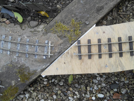
The angled end of the bridge, showing the rails either side stopping short of the gap
The short drop-in section of track to complete the circuit
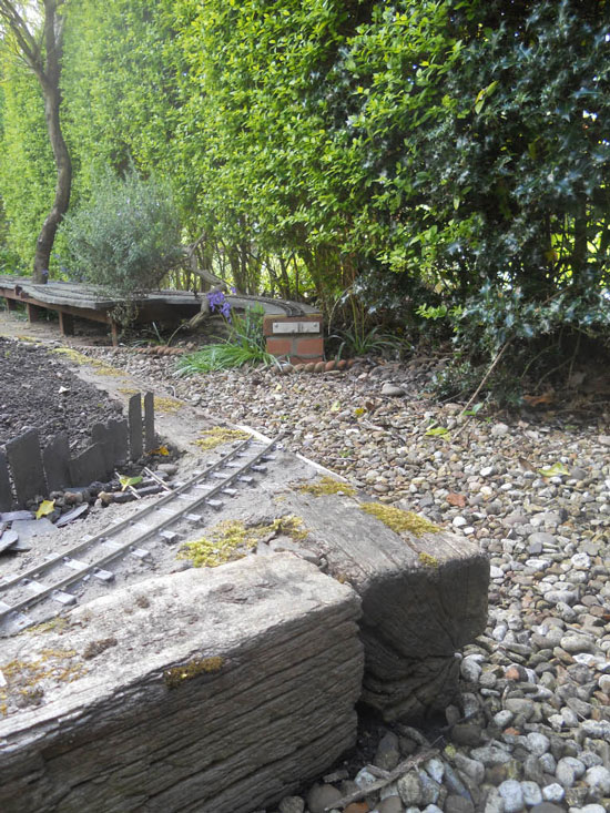
Is it finished? Of course not… The original bridge has prominent handrails (metal on the current bridge, timber on the original) which I may one day add, though they would obviously be a target for those stepping over the bridge to follow their train around the garden. I had planned to add a representation of the longitudinal beams which support the track under the deck, thus hiding the aluminium box section – that too has not happened yet. And really the whole thing could do with a bit of weathering; it lives in our shed most of the time, so has not had the full force of the English weather to kick-start the process.
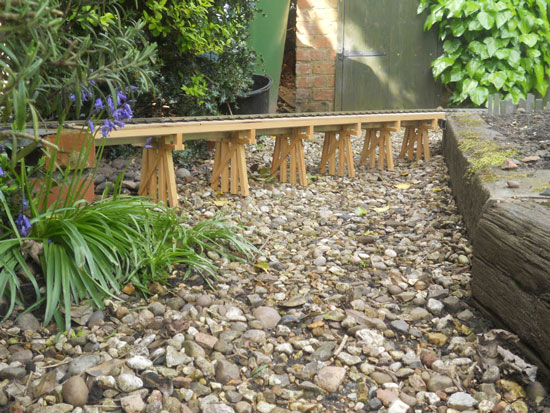
The finished (well, nearly) bridge
Richard Huss